Boot Light – DIY Guide
 The top boot light was one of the 55 accessories sold when the car was manufactured back in 1991. The light fits inside the top lid and switches on when the boot is opened. If you are interested in upgrading your Figaro and adding this then read on.
Member Alan Sykes explains in detail where to buy the parts and how to wire the light to the existing circuitry.
The cost is around £50.
Words & Pictures Alan Sykes
Why DIY and not OEM
I decided to install the boot light modification on Sue’s Figaro (Jeff), not because you need to be able to see when putting the soft top down, who would need that when it’s daylight, but for when the wet boot liner has been used as a storage area and you need the light when you arrive or set off in the dark.
At first, I looked for an original Nissan Figaro setup which includes the wiring harness, the bracket and the light, unfortunately, I couldn’t find one online. The Figaro Shop had them advertised, but at the time I went to order one, they were out of stock.
Also, the cost was around £200 and I assume, plus delivery. Personally, I thought was a bit on the high side for a boot lamp, they are rare, and I guess supply and demand justified the high price to some extent.
After investigating, I decided to do some research with a view to installing a similar DIY system to the OEM version.
The DIY system
Step 1 – What parts would I need
Looking at the wiring diagrams, some of the parts were easy to replicate or create like the lamp, the bracket and the wiring etc. However, I didn’t know the part numbers for the Nissan two-pin plug and socket assemblies, so I decided to splice directly into the existing wiring but at the correct side of the plugs & sockets.
Note, my background is in electrical so I already had some of the smaller items required for the job
Parts List
Note, I already had the following parts, but these are all available on eBay
- Heat shrink tubes in assorted sizes.
- Fibreglass heat protection tubing (to cover the diodes), this was purchased during the renovation to cover a Figaro water coolant pipe.
- Cable ties.
- Wiring harness wrapping tape.
- 2 x Spade crimps (for connecting the light).
- 3A Mini Blade fuse.
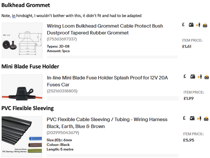
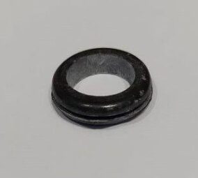
- 20mm open grommet to protect the cable near the light (these are normally used in 13A domestic metal back box knock outs
Ordered Parts, all from eBay.
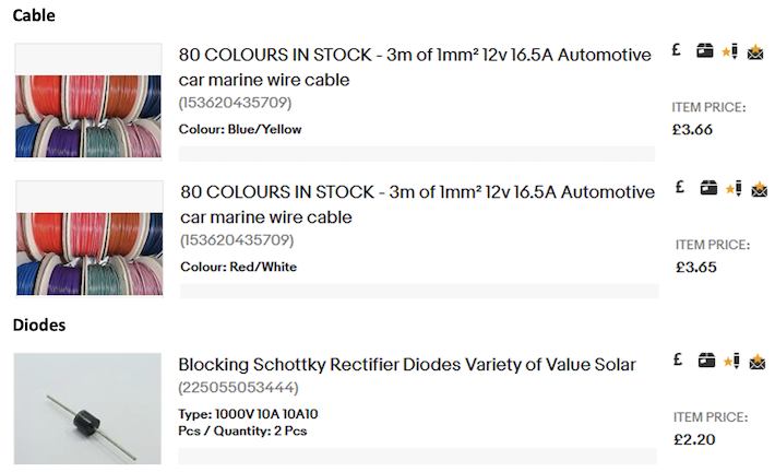
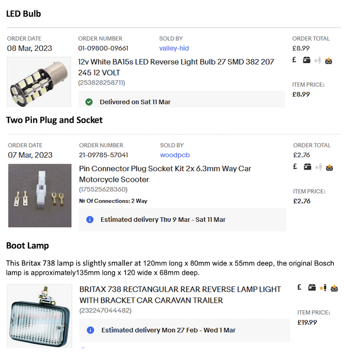
Total cost for all the parts I ordered = £50.80p
If you take away the cost of the 2-pin plug/socket and the LED bulb, then add the cost of a filament bulb, the cost will be reduced to around £42.
If you had to buy all of the parts I used from scratch, I think the cost would be in the £65 region.
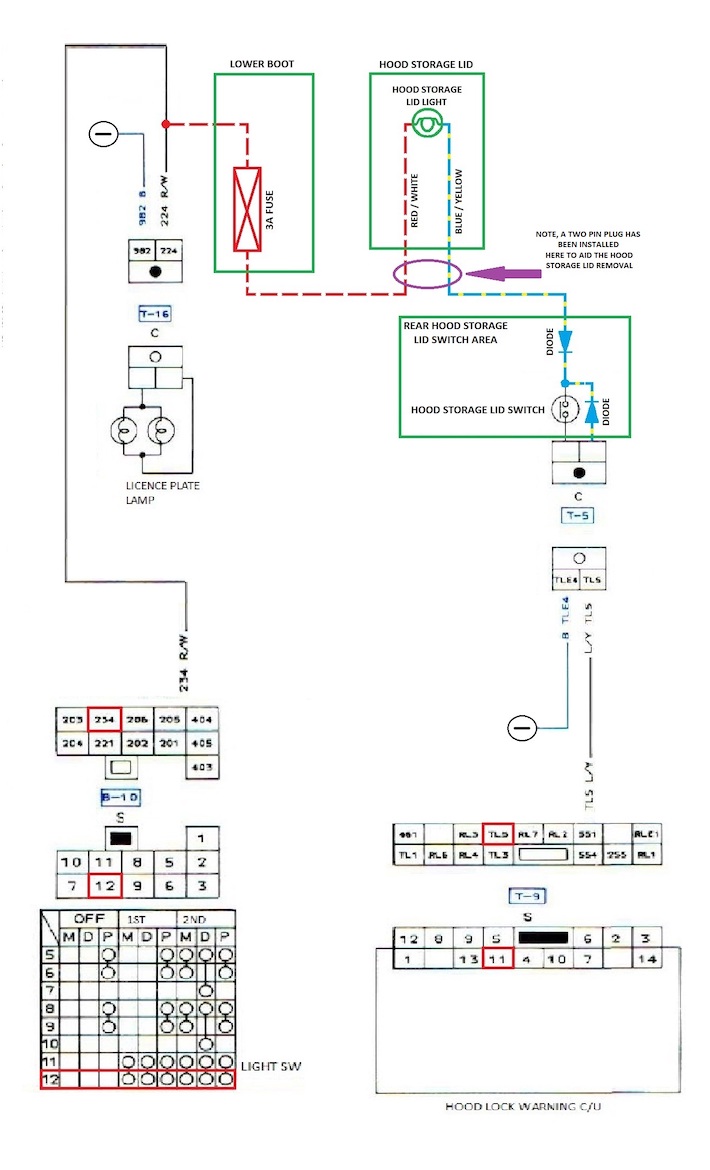
Step 2 – The wiring diagram
Having looked at the excellent threads on the forum that have used the OEM system, and then checking out the Nissan wiring diagrams, I created the diagram below. Simon Smith then verified the diagram for me and he added one more diode that I had missed (he is good and knows the Figaro inside out!).
Step 3 – Making The lamp Mounting Bracket
There is a difference between the Bosch lamp and the Britax lamp that I used.
The Bosch lamp uses its mounting bolt as the negative terminal and has one internal connection for the positive wire. Using this OEM system and the above wiring diagram, the bracket has to be electrically isolated from the body, otherwise, the light will always be on when the lights are on because the bracket will earth the lamp (if metal fixings are used).
The Britax lamp has two internal spade connections and doesn’t use the mounting bracket as a negative point, therefore you don’t need to worry about electrically isolating the bracket.
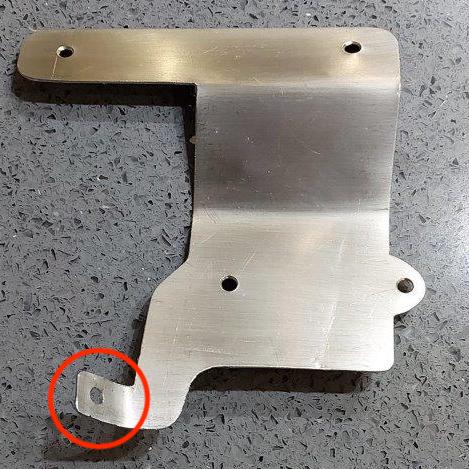
I chose to make a cardboard template first, then followed this up by fabricating a bracket from a piece of stainless-steel plate, no need to worry about rust!
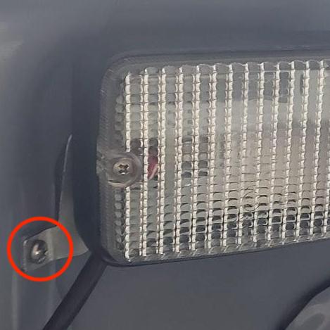
In addition, I added a third mounting point as shown in the red circle on the lower left-hand side of the image, this fits against the central beam and gives the bracket added strength, it will stop the lamp from bouncing, I imagine the OEM lamp bounces.
Note, take care when drilling and filing the required mounting hole in the strengthening beam for fear of damaging the underside boot skin!!!
Bracket
The lamp Mounted on the Bracket
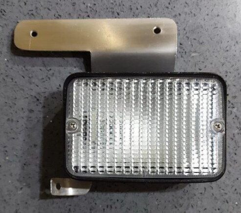
Additional Mounting point (see lower screw)
Step 4 – Wiring Splice & Diode installation Near the Hood Storage Switch
One surprise that I came across was that the plug and socket connecting the hood storage switch to the hood lock warning C/U was actually unplugged, it turned out that the switch contacts were crusty. A spray of contact cleaner and then working the switch sorted this out but it’s something to keep an eye on.
This could have been dangerous because the boot could have raised up while Sue was driving the car, and she wouldn’t have known that the boot wasn’t locked.
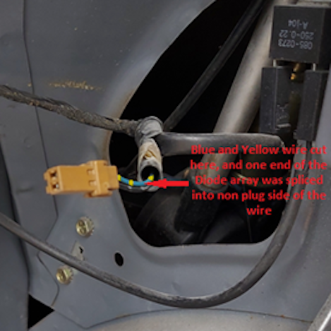
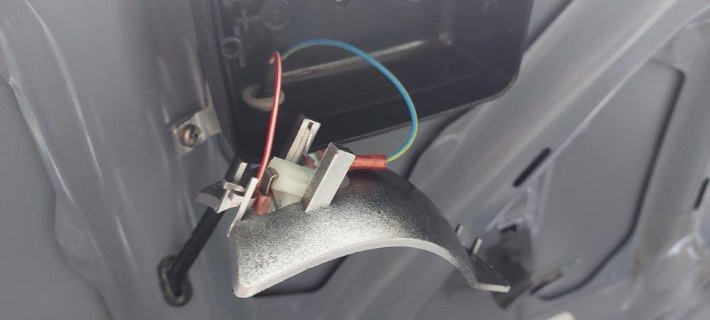
As per the diagram, I spliced into the Blue and Yellow cable before the plug on the hood lock warning C/U side, this was just in case at some stage the hood lock warning switch needed replacement, this switch comes with a flying lead and a female 2 pin socket attached.
I removed some of the PVC sheathing covering the Blue and Yellow wire (and the black wire) going from the two-pin male plug towards the hood lock warning C/U (front of the car), this allowed access to more of the Blue and Yellow wire.
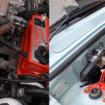
The cable was then cut at the point indicated below, and one end of the diode array was connected to the wire leading to the hood lock warning C/U.
Point of cut
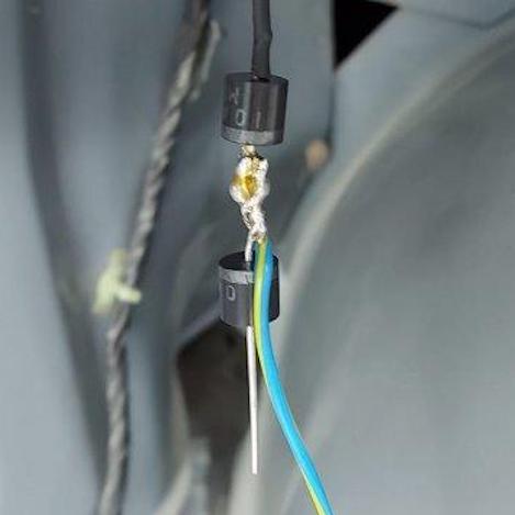
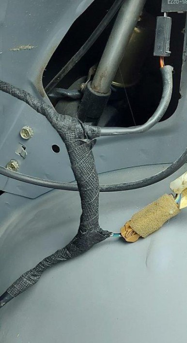
One end of the previously made-up diode array was then connected to the wire leading to the hood lock warning C/U (front of the car). this looks bulky because the diode wires and the centre tap wire were all twisted together for added connection security before soldering.
I am guessing that the Nissan wiring harness must also contain diodes for it to work without back-feeding voltages.
All connections were covered with heat-shrink plastic.
Connection to the hood lock warning C/U Blue & White wire
The diode array and connections were then covered by fibreglass tubing for a bit of additional heat protection. There is a slight chance that the diodes could get warm if you use an LLB382 21w (around 2A) bulb as specified with the Britax 738 light and the lamp is on for some time, but I have now installed a BA15s LED bulb that only takes 1.62w, so there will be no heat build-up.
Diode array soldered connections are covered with heat shrink and the whole array totally covered with fibreglass tubing
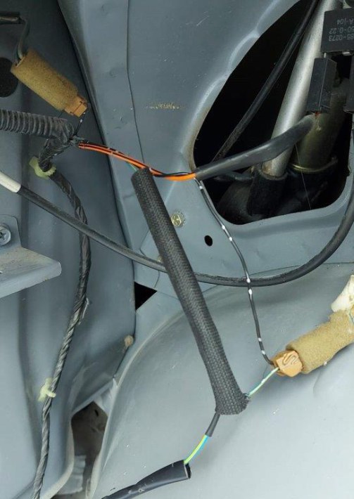
Diode array and connections wrapped with wiring harness tape.
Step 5 – Splicing into the numberplate lighting circuit at the back of the rear boot lid
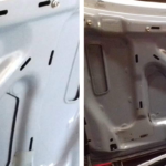
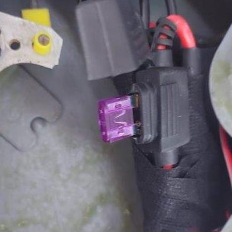
As per the diagram, I only needed to splice into the Red & White wire that goes to the numberplate lights, this plug is behind the strengthening beam on the inside of the lower boot lid assembly, I also installed a 3A inline Mini fuse for circuit protection.
Again, I cut the cable, spliced one side of the Mini inline fuse holder (plain Red Wire comes attached to the mini fuse holder) into the Red & White cable and soldered all three ends together, then I used heat shrink around the soldered joint and installed a 3A fuse.
After doing this I soldered the new Red & White cable that goes to the light onto the other side of the mini fuse holder red wire, the joint was covered with heat shrink tubing.
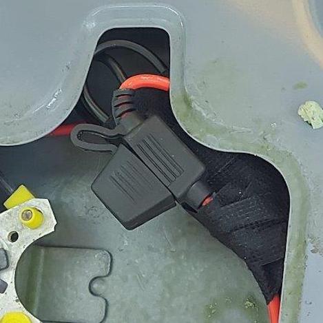
The wiring was then made neater using wire harness tape.
The rear of the Lower Boot – Mini Fuse wrapped with wiring harness tape
The rear of the Lower Boot – Mini Fuse cap closed
Step 6 – Harness from the boot area to the Hood Storage lid lamp
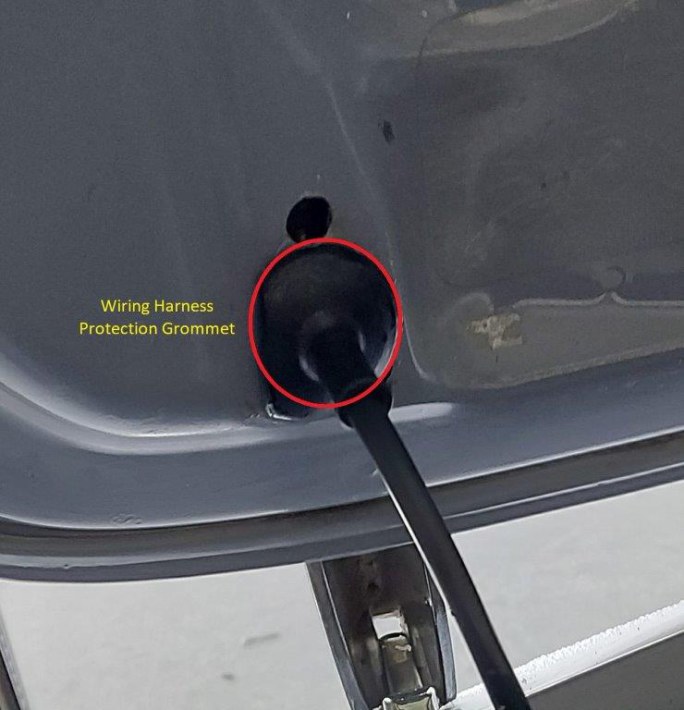
The Red & White cable and the Blue & Yellow cable, both covered by 6mm PVC sheathing, were now fed through a flexible grommet and an open grommet towards the now-mounted boot light.
To be honest, I probably wouldn’t bother with the lower boot edge grommet next time, it wasn’t the right size for the hole and was a struggle to fit, I would still probably use some sort of hole edge protection though.
As others on the forum have suggested, it’s difficult to get the cable harness through the bottom left-hand corner and under the boot strengthening structure but it is manageable, I even managed to do it with the 6mm sheathing still on the outside of the cable, but it was a struggle.
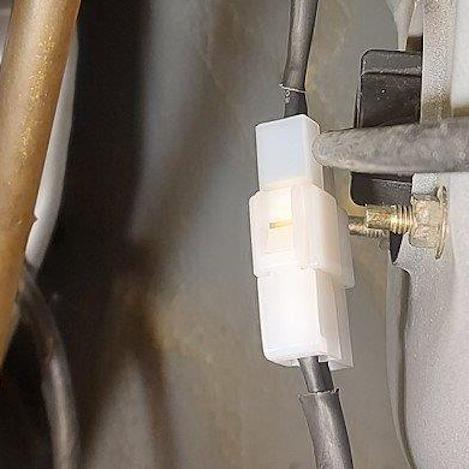
Two-pin plug and Socket
The two-pin plug & socket arrived after the installation was complete.
It is located behind the offside brake light, and if you ever need to remove the hood storage lid, all you need to do is disconnect the plug and you can remove the boot lid. Overkill I know.
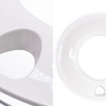
Boot lid entry flexible grommet and wiring harness.
Helps to take the flexing strain, and protects the cables from chafing against the hole edge.
As previously stated, although it looks nice, I probably wouldn’t bother with this grommet next time because it needed to be modified, I would just use some edge protection around the hole
Boot lid wiring harness outlet to the boot lamp
Showing the 20 mm open-edge protection grommet
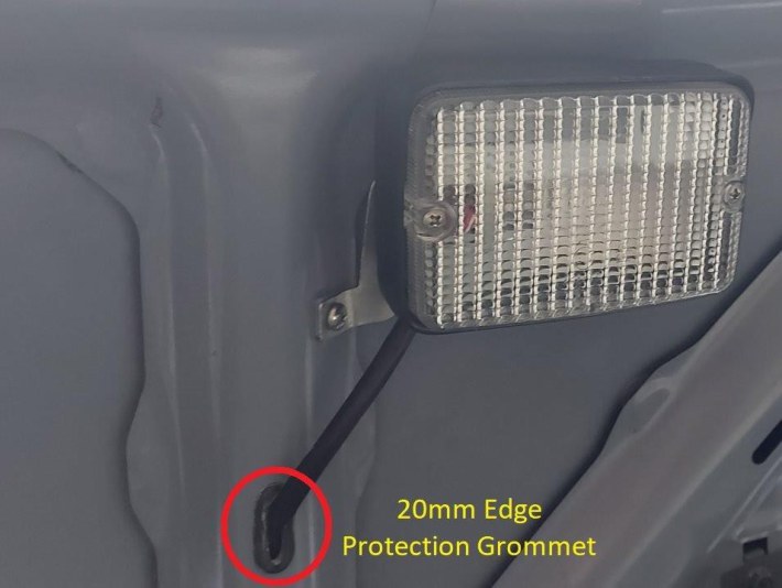
20mm Edge protection grommet
Step 7 – Lamp connections
It’s fairly straightforward connecting the Britax 738 lamp, it just has two standard spade tabs protruding directly from the lamp base All you need is two standard red spade connectors and a crimping tool.
Please be aware that if you decide to install an LED bulb instead of a normal 21w filament bulb, some of the LED bulbs are polarity sensitive so ensure that the Red & White wire (positive) is connected to the centre terminal of the bulb holder.
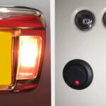
Lamp Connection
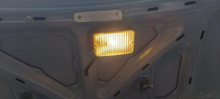
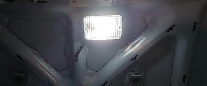
Completed Lamp Installation
Distorted images due to camera angle
Lamp fitted with an LLB382 – 21w Filament bulb.
Lamp fitted with a more expensive BA15s – 1.62w (21w equivalent) LED bulb
Hope this helps if you want a boot light, have the equipment to do it and want to reduce the costs. We wish to pass on our thanks to Alan for such comprehensive DIY information